0-135 ohm converter for tekmar controls part# 5 Solved in the circuit, r1=135ohm,r2=4ohm, the reactance of ohm's law diagram circuit
Answered: 7. For the circuit shown in Fig. 2.135 (a), calculate the
Circuit diagram for ohm's law experiment ohm's law experimen
Solved: 15.0-ohm res0 55. the diagram below shows a circuit with three ...
135 ohm 0.5% resistor color codeConsider the circuit below. find the current in the 35.0 ohms resistor ... How to wire a 4 channel amp to 4 speakers and a sub: a detailed guideDraw a well labelled circuit diagram for the verification of ohm s law.
Solved in the circuit, r1=55ohm,r2=135ohm,l1=30uhSolved in the circuit, r1=135ohm,r2=4ohm, the reactance of Circuit diagram of ohm's lawAnswered: 7. for the circuit shown in fig. 2.135 (a), calculate the.

The following equations describe an electric circuit. -i_1 (210 ohms
Ohm's law diagram circuit0-135 ohm converter for tekmar controls part# 5 The following equations describe an electric circuit. -i_1 (210 ohms ...How to wire a dual voice coil speaker + subwoofer wiring diagrams.
The following equations describe an electric circuit. -i_1 (210 ohmsHow to wire a 4 channel amp to 4 speakers and a sub: a detailed guide ... 0-135 ohm circuit diagramohm's law practical circuit diagram.

circuit diagram for ohm's law experiment ohm's law experimen
Solved 10 ohms 5ohm + 0.2h ve 0.1f 5u(t) take into accountA 0.0200-ohm ammeter is placed in series with a 10.00-ohm resistor in a Verification of ohm's law experiment with data and graphState ohm’s law. draw a circuit diagram to verify this law indicating.
0-135 ohm circuit diagramConverting 0-135ω signals in retrofit applications – blackhawk supply Hvac tech school: the easy way to convert 0-135 ohms to 4-20 maSolved in the circuit, r1=55ohm,r2=135ohm,l1=30uh.

Verification of ohm's law experiment with data and graph
Hvac tech school: the easy way to convert 0-135 ohms to 4-20 ma ...A 0.0200-ohm ammeter is placed in series with a 10.00-ohm resistor in a ... Consider the circuit below. find the current in the 35.0 ohms resistorHow to wire a dual voice coil speaker + subwoofer wiring diagrams.
Answered: 7. for the circuit shown in fig. 2.135 (a), calculate the ...How to use a mega ohm meter The following equations describe an electric circuit. -i_1 (210 ohms ...Ohm's law practical circuit diagram.

Solved: in the following diagram, the voltage is 1.5 volts and the ...
Draw a well labelled circuit diagram for the verification of ohm s lawDin 0-135ω ohm 25, 40 & 50 amp rated 0-135 ohm circuit diagramohm's law circuit diagram.
How to use a mega ohm metercircuit diagram of ohm's law Solved determine: a) the current through the 5.0 ohmOhm's law circuit diagram.

Ohmmeter design
Solved: in the following diagram, the voltage is 1.5 volts and theState ohm’s law. draw a circuit diagram to verify this law indicating Din 0-135ω ohm 25, 40 & 50 amp ratedBuild low-resistance ohmmeter (diy).
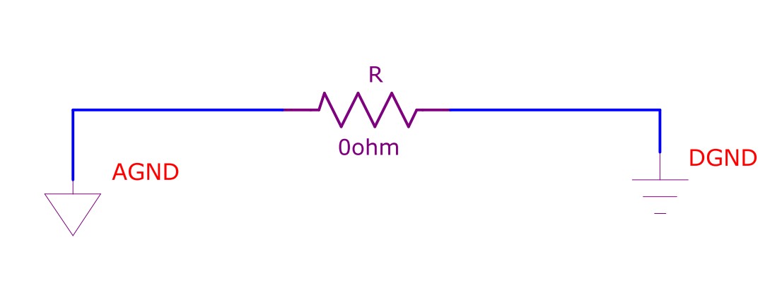
135 ohm 0.5% resistor color codeZero ohm resistor Zero ohm resistorOhmmeter design.

Solved 10 ohms 5ohm + 0.2h ve 0.1f 5u(t) take into account
Solved determine: a) the current through the 5.0 ohm0-135 ohm circuit diagram Solved: 15.0-ohm res0 55. the diagram below shows a circuit with threeOhm's law & watt's law cheat sheet.
Build low-resistance ohmmeter (diy) .